Add Wire
The Add Wire menu can be used to add wires with different physical properties, and attach objects together.
Warning
After a wire is added to the simulation, its nodes cannot be further re-positioned. Very small positional adjustments can be made by temporarily disabling physics, but this is strongly discouraged as it can have unintended consequences and break a scene.
Add Wire Menu


Adding a Wire
Before adding a wire, the wire type property must be selected from the available presets:
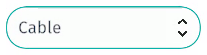
Below are the available wire type options:
Wire type |
Mass density |
Mass per meters |
Visual type |
|---|---|---|---|
Cable |
7800 |
15.3152641862502 |
CABLE |
Chain |
1965 |
3.85826847768997 |
CHAIN |
PSVHose |
800 |
1.5707963267949 |
PSVHOSE |
Wiresling |
7800 |
15.3152641862502 |
WIRESLING |
DiverUmbilical |
1025 |
2.01258279370596 |
DIVERUMBILICAL |
ROVUmbilical |
1025 |
2.01258279370596 |
ROVUMBILICAL |
Fiber |
1025 |
2.01258279370596 |
FIBER |
HPMEFiber |
1000 |
1.96349540849362 |
HPMEFIBER |
Note
Toggle the
 button to dynamically visualize the tension of a wire by applying a gradient texture to the wire. Tension gradient will show as a translucent tube around a wire. Tension visualization can also be toggled On/Off in the
 Input ports in the Properties Panel.
After a wire type has been selected, click
 to continue to the
 Wire Node menu. In the next menu, click
 and you get presented with 2 options:
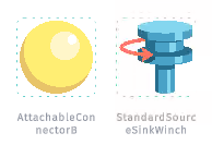
To create a wire in Sandbox, 2 endpoints are needed. To create a basic wire between 2 points, use 2 AttachableConnectors
 . If the wire needs to be pulled in or out from an end node, then use a combination of
 AttachableConnectors
and StandardSourceSinkWinch
 .
.
Adding and Connecting Nodes
Left-click
 on a node (
or
), then drag it out to the scene and place it on intended object.
on a node (
or
), then drag it out to the scene and place it on intended object.Click
and drag the second node (
or
) to the intended object for the end point.A node’s position can be adjusted by clicking on the blue ghost node and using the gizmos to move it in the desired direction. Pressing the
Delkey on the keyboard will delete a selected node.When nodes are positioned to intended locations, click
 to connect the 2 nodes and create the wire.
Wires From Existing Nodes
Wires can also be created by using existing nodes and a wire node can connect to multiple wires. To create a wire from two existing existing nodes, follow these steps:
Wire Collision
By default, wire collision is disabled and wires will not react to other objects in a scene. To enable collision on a wire, first select the wire by left-clicking
on the white ball located in the middle of the wire.
The settings for the wire is now displayed in the Properties Panel. Expand Input Ports to find the Collision enabled toggle button. Set the Collision enabled toggle button to “On” position to enable wire collision. Toggle to “Off” position to disable wire collision.
Wire Diameter
A wire’s diameter can be adjusted to make its representation more realistic when operating with large dimensions. The wire’s Diameter value can be set in the Output ports. It can be set using the following units:
Unit |
Unit non-abbreviated |
Default |
|---|---|---|
m |
Meter |
Yes |
NM |
Nano Meter |
|
mm |
Millimeter |
Wire Visual Type
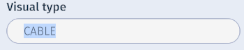
A wire’s visual type can be set by typing in one of the visual types listed in the table above into the Visual type port in the Input Ports.
Other Wire Settings
Type |
Setting |
Value |
Default |
Description |
|---|---|---|---|---|
Toggle button |
Visualize tension |
Off/On |
Off |
Enable to visualize the tension in the wire |
Toggle button |
Wind enabled |
Off/On |
Off |
Enable to to make wire affected by wind. |
Deleting Wires
To delete a wire, simply right-click
 on the wire node located at the middle of the wire (white ball) and select
 from the context menu. A wire can also be deleted by selecting the wire node and pressing the
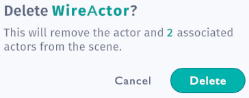
 Del key on the keyboard. Before a wire is deleted, you must confirm by selecting Delete from the prompt:
Note
Deleting a wire does not delete the wire or winch nodes. To completely remove a wire you must also delete the associated nodes. There is however no harm leaving unconnected nodes in a scene.
Using Winches
In order to operate a winch, the corresponding WinchActor must be selected. Please make sure that the
 checkbox in the Constraints is checked so that the winch node is visible.
A winch node is visualized as a blue box. This box can be re-sized by holding the
checkbox in the Constraints is checked so that the winch node is visible.
A winch node is visualized as a blue box. This box can be re-sized by holding the V key while scrolling the middle mouse button
 .
.
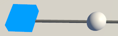
Winch actor node is represented by a blue box.
Once a winch actor is selected by left-clicking
the blue winch node, the settings are displayed in the Properties Panel.
Paying In and Out
A winch is controlled from the Properties Panel’s Input Ports. This is also where all aspects of a winch can be controlled or adjusted.
There are 2 ways of paying in or out wire on a winch: Commanded speed and Commanded speed %. Use the Speed mode setting to change between the two modes.
|
Speed Mode |
Default |
|---|---|---|
0 |
Commanded Speed |
Yes |
1 |
Commanded Speed % |
Commanded speed
The default value for Commanded speed is 0, which means neither paying in nor out wire. A negative value will pay in wire, while a positive value will pay out wire. The Max value property is ignored in this mode.
Available units for Commanded speed are:
Unit |
Unit non-abbreviated |
Default |
|---|---|---|
m/s |
Meter per second |
Yes |
kn |
Knots |
|
km/h |
Kilometer per hour |
Max speed
The Max speed value specifies the maximum speed that the winch can operate given the chosen unit. This value is only applicable for the Commanded speed % property.
Available units for Max speed are:
Unit |
Unit non-abbreviated |
Default |
|---|---|---|
m/s |
Meter per second |
Yes |
kn |
Knots |
|
km/h |
Kilometer per hour |
Commanded speed %
The default value for Commanded speed % is 0. Make sure that the Speed mode is set to 1 in order to utilize this speed mode. The Commanded speed % value is relative to the Max value property value.
Available units for Commanded speed % are:
Unit |
Details |
Range |
Default |
|---|---|---|---|
% |
Specify a percentage |
0-100 |
Yes |
0-1 |
Specify a decimal |
0-1 |
Commanded max in force
The Commanded max in force property specifies the maximum force in which the winch operates. This value can be entered by using the following units:
Unit |
Unit non-abbreviated |
Default |
|---|---|---|
N |
Newton |
Yes |
kN |
KiloNewton |
|
ton |
Metric ton |
Commanded max out force
The Commanded max out force property specifies the maximum resistance in which the winch operates. This value can be entered by using the following units:
Unit |
Unit non-abbreviated |
Default |
|---|---|---|
N |
Newton |
Yes |
kN |
KiloNewton |
|
ton |
Metric ton |